 | ||
| TRIP COMP Here is my guide on how to add LED backlighting to your trip computer (should be the same process for EF/EL trip comps and similar to what has to be done for instrument cluster illumination. this is a GUIDE only, some things you have to figure out yourself.
You will need:
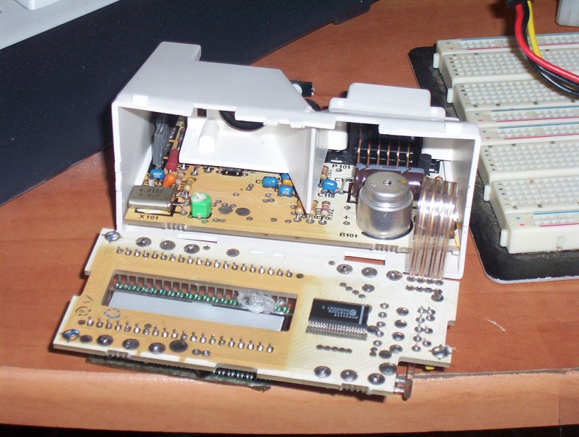
4 5mm ultrabright LEDs (in your chosen colour) soldering iron, solder, etc etc Ive since re done my trip computer, it now uses only 3 10mm ultrabright LED's each with a current limiting resistor First up you have to crack open your trip comp, the front black part simply clips on and can be easily removed, Next you have to remove the three plastic light guide things, i did it with a hot soldering iron (do this in a well ventilated area) use a bit of cardboard to protect the LCD screen and plastic diffuser. this is what you have once youve done the above steps:
Next you have to make a reflector assembly to create a better light behind the LCD screen, i used some aluminum foil glued to cardboard to make mine. You cant see it in the pictures but the front of the reflector is flsuh with the back of the LCD. See the following picture for more detail:
Now get the 4 5mm LEDs and sand the round end off them to about 2 mm above the metal bits inside:
Now get three of these LEDs and glue them into the reflector like so: (note the fourth one on the RH side of the reflector, you can see its legs sticking up, it is in the front of the trip comp, under where the instL/100,AVGL/100 etc is):
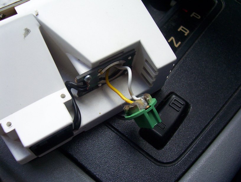
EDIT - originally i had them in series, there ended up being a problem with thermal runaway and the LEDS stopped working (this pic is incorrect but you get the idea) Now solder the Resistors to the + leg of each LED and run them all in parralell. add 50mm of wire to the now paralell LED's post the two wires (positive and negative) from the LEDs out the back of the trip comp, and join them into the globe holder, plug it in (100% chance of getting the polarity wrong first go):
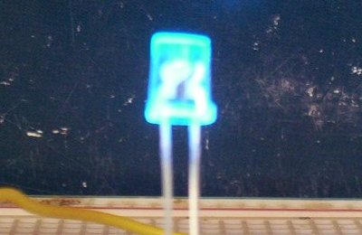
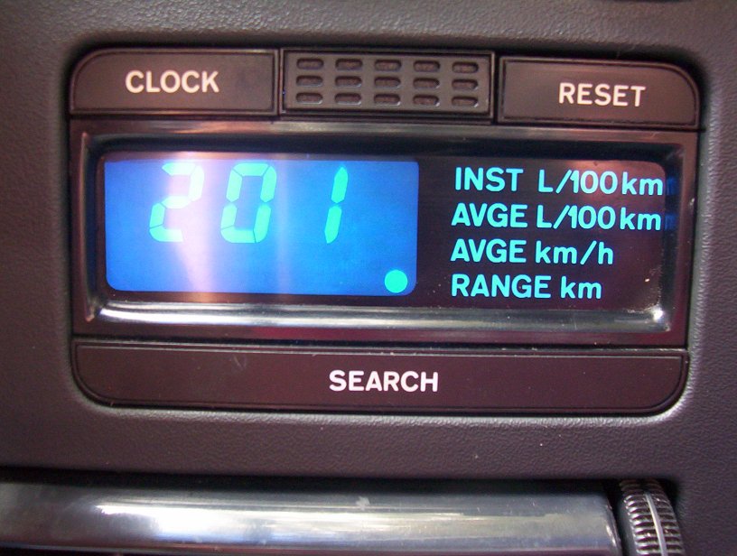
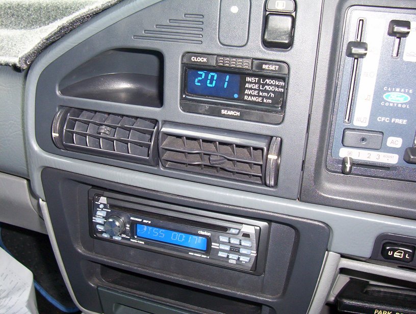
TEST the trip comp before you go and put your dash back together to check that its all working, if you got the globe holder the wrong way around it wont work, if it doesnt, swap the way you have it in. the finished product looks like this:
I didnt quite get the 3mm LEDs in the right spot, so they dont light the buttons up properly, you have to be carefull how you route the wires for them too because there isnt a lot of room. I wrote this as a GUIDE only, please dont email me if you cant figure it out, i dont want to have to explain the theory behind electronics to 100 people, if you dont understand my instructions and cant figure out your own way, you shouldnt be doing this in the first place. REMEMBER LEDs blow up if they are put across 12 volts, thats why they are in strings of 4 (so the volt drop across each is 1/4 the supply voltage) LEDs are polarised, so if you get the legs mixed up they wont work. Its not my fault if YOU attempt this and screw up, so be sure you know one end of a soldering iron from the other before you start. |